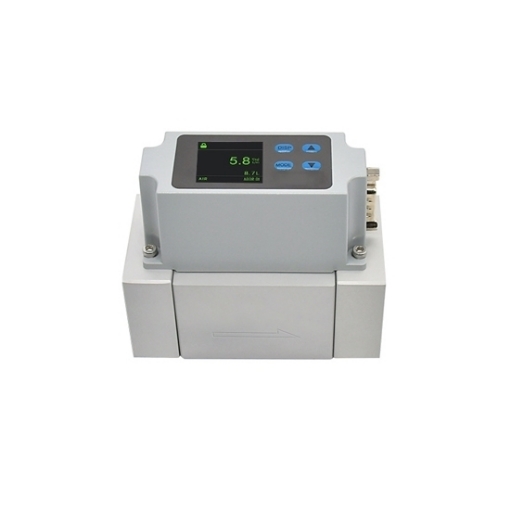
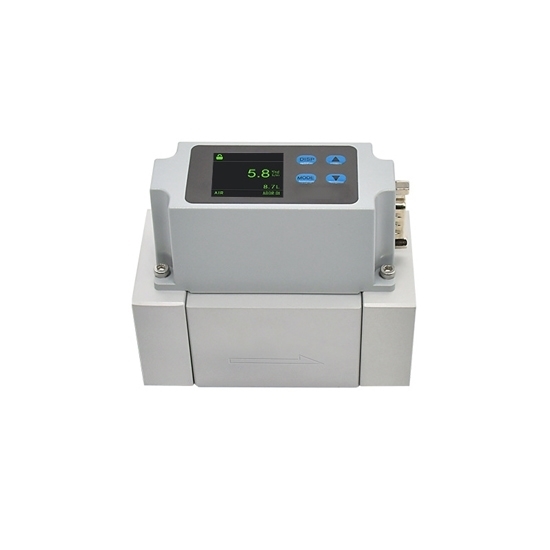
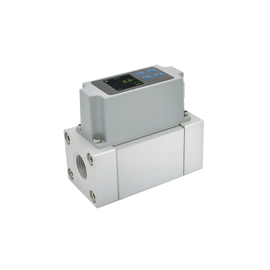
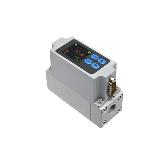
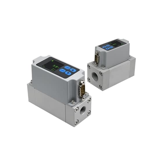
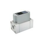
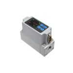
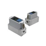
Thermal Gas Flow Meter, 0~2/20/100L/min, RS485 Modbus
Original price was: $455.63.$45.99Current price is: $45.99.
The thermal gas flow meter with RS485 Modbus interface offers a comprehensive solution for laboratory, industrial, and IoT gas measurement. Three selectable flow ranges: 0.02-2 L/min, 0.2-20 L/min, and 1-100 L/min, allow precise measurement across diverse applications with a single device.
Specification
| Model | T-AMS1000A02 | T-AMS1000A01 | T-AMS1000A03 |
| Accuracy |
±4% RD (0.02‑0.5 L/min) ±2% RD (0.5‑2 L/min) |
±4% RD (0.2‑20 L/min) ±2% RD (5‑20 L/min) |
±4% RD (1‑25 L/min) ±2% RD (25‑100 L/min) |
| Measuring Medium |
Dry, clean, and non-corrosive gases such as air, oxygen, argon, nitrogen, and carbon dioxide (excluding flammable and explosive gases) |
||
| Maximum Working Pressure | 0.8 MPa | ||
| Nominal Diameter | G1/4 | ||
| Working Temperature | -10 ℃ – +60 ℃ | ||
| Repeatability | ±1% F.S. | ||
| Response Time | 50 ms | ||
| Standard Calibration Gas | Air (25 ℃, 1 standard atmospheric pressure) | ||
| Signal Output | Default RS485+4-20 mA/RS485+1-5 V (optional) | ||
| Communication Method & Protocol | RS485, MODBUS‑RTU | ||
| Power Supply | <0.85 W | ||
| Display Mode | LCD display | ||
| Housing Material | PC | ||
| Duct Material | Aluminum | ||
| Net Weight | Approx. 330 g | ||
Key Features
- ±2% RD accuracy ensures reliable experimental results and process control.
- 50 ms response time captures real-time flow fluctuations for dynamic automation environments.
- Three selectable ranges cover both low-flow leak detection and high-velocity industrial demands, reducing inventory costs.
Dimension (unit: mm)
Structure
Interface Definition
| Pin | Lead Wire Color | Definition |
| 1 | Orange | External output 1 |
| 2 | Brown | Analog output |
| 3 | Green | RS485B |
| 4 | Yellow | RS485A |
| 5 | Red | Power supply cable |
| 6 | Black | GND |
| 7 | Blue | GND |
| 8 | Purple | GND |
| 9 | Gray | External output 2 |
| / | Transparent Heat Shrink Sleeve | Shielded cable |
Piping Methods
Straight pipe requirement – For the tubing connected to the inlet and outlet ports of the AMS1000 series, always reserve the straight pipe section as specified in the table below. Failure to do so may cause an accuracy deviation of ≥3% F.S.
Orientation of the flow meter duct – The duct of the T-AMS1000 series should be installed either parallel or perpendicular to the horizontal plane.
- When installed parallel to the horizontal plane, the device interface must be positioned above the duct and also parallel to the horizontal plane.
- For other installation angles, please contact our customer support.
This thermal mass flow meter for air (RS485 Modbus) requires the following straight pipe lengths: for AMS1000A01/A02/A03 – inlet ≥12.5 cm, outlet ≥6.25 cm.
Application
FAQ & Solutions for Thermal Mass Flow Meter
| Question for Thermal Mass Flow Meter | Solutions for Thermal Mass Flow Meter for Natural Gas |
| Flow rate reading is inaccurate – too high, too low, or no flow at all | Check if the piping meets the requirements in the datasheet |
| Verify that the gas type being used is correct | |
| Ensure the gas pressure meets the minimum driving standard of 0.1 MPa | |
| Make sure the installation environment is free from vibration or interference | |
| Inlet and outlet pipe requirements | For accurate measurement, the inlet of the gas mass flowmeter must be connected to a sufficiently long straight pipe. Refer to the datasheet for detailed installation instructions. The installation area should be free from vibration and electromagnetic interference |
| Different readings from two flow meters on the same pipeline due to different positions | Different positions along the same pipeline experience different flow resistance (pressure drag), which can cause significant reading variations. To minimize this, ensure consistent installation orientation and sufficient straight pipe sections |
| What types of gas can this flow meter handle | This thermal mass meter is designed for single-component gases only. Mixed gases cannot be measured accurately. The gas must be dry, clean, and free from moisture or oil vapor |
AMS1000 Troubleshooting – Thermal Mass Air Flow Meter
| Fault Indication | Possible Cause | Corrective Action |
| No display on the main interface |
|
|
| Non‑zero instantaneous flow reading before measurement |
|
|
| No flow recorded |
|
|
| Reduced flow reading |
|
|
| Communication failure |
|
|
| Flow Range * | , , |
|---|---|
| Output Signal * | , |
| Accuracy | , |