Sale
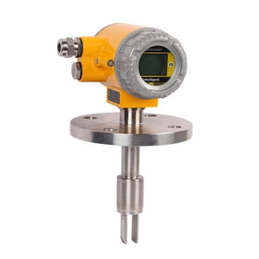
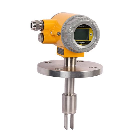
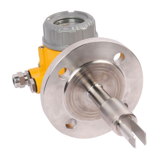
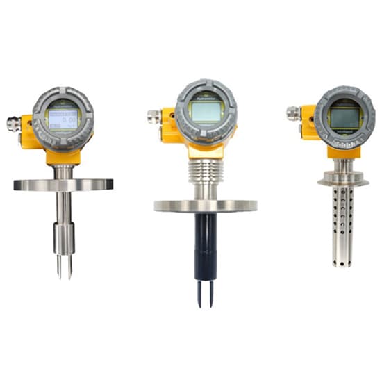
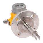
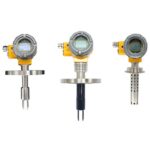
Tuning Fork Density Meter, LCD Display, 0 to 2.5g/cc
Original price was: $2,964.00.$296.99Current price is: $296.99.
18
People watching this product now!
Description
The tuning fork density meter provides a wide range of measurement from 0 to 2.5g/cc to meet specific industry needs. It uses an LCD display, the measurement data is intuitive and readable, and the stainless steel or aluminum shell protects the measuring tube and the drive detection device. The tuning fork density meter is equipped with a digital sensor and PT100 temperature compensation.
Feature
- The transmitter uses an acoustic frequency signal source to excite the metal tuning fork.
- The housing is made of stainless steel or aluminum to protect the measuring tube and the drive detection device.
- The tuning fork vibrates freely at the center frequency, and the liquid can be measured by analyzing the frequency.
- LCD large screen display, intelligent reading, measurement data is clear at a glance, intuitive and readable.
- Optimized material, high corrosion resistance, greatly enhanced service life.
Specification
| Model | T-LDM025 |
| Measuring range | 0-2.5g/cc (0-2500kg/m3) |
| Measuring accuracy | ±0.5% |
| Operating temperature range | -50℃~+150℃ |
| Maximum working pressure | 4mpa |
| Fluid viscosity range | 0-2000cP |
| Built-in temperature sensor | Digital sensor, PT100 temperature compensation |
| Liquid contact material | 316L, 2205, 2507 stainless steel, etc. |
| Power supply | 24V DC, ≥50mA |
| Display mode | LCD display |
Product Details
Installation Method
| Installation standard | T-shaped side opening, Plug-in installation | T-shaped side opening, Retracted installation |
| Note | The fork body part directly enters the main fluid | The fork body is retracted into the side opening of the pipe to avoid the main flow, and is retracted by 25mm |
| Flow speed | The flow speed through the fork is 0-1m/s | The flow speed in the main pipe is 1-5m/s |
| Viscosity range | Maximum 600cP | Maximum 100cP (can reach 250cP in individual cases) |
| Temperature | -50-150℃ | -50-150℃ |
| Main pipe size |
≥ horizontal pipe 100mm (4”) ≥Vertical pipe 150mm (4”) |
≥50mm (2”) |
| Not suitable for |
|
|
Tips: Notes on using a tuning fork density meter
Unlike pipeline density sensors, the fork body of the insertion type densitometer (concentrator) is not fully enclosed.
- Pipe wall or container: The wall will produce boundary effects on the fluid plus the viscosity effect of the measured medium itself, which will have a certain impact on the measurement calibration of the sensor.
- Installation positioning: In order to ensure that the density meter can measure accurately and display stably, the flow rate of the measured medium shall not be greater than 1m/s, and the diameter of the pipeline where the density meter is installed shall be greater than or equal to 159mm. The location where the density meter is installed should be as far away from the pump as possible, and the distance should preferably be greater than 5m; when the flow rate is greater than 1m/s, the expansion installation is adopted. For every increase of 1m in the flow rate, the diameter of the pipeline where the density meter is installed is expanded by 1.5 times. There must be a straight pipe section of > 600mm in front of the meter and a straight pipe section of > 300mm behind the meter to ensure that the fluid is in a laminar state when flowing through the fork body.