Sale
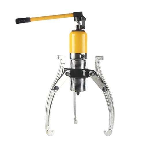
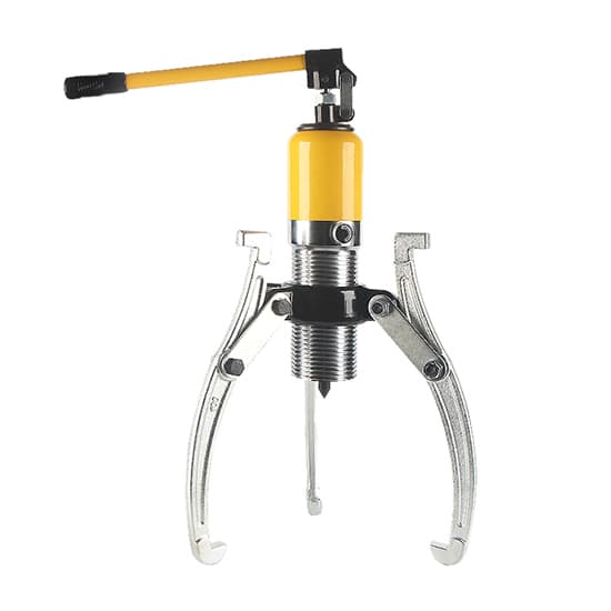
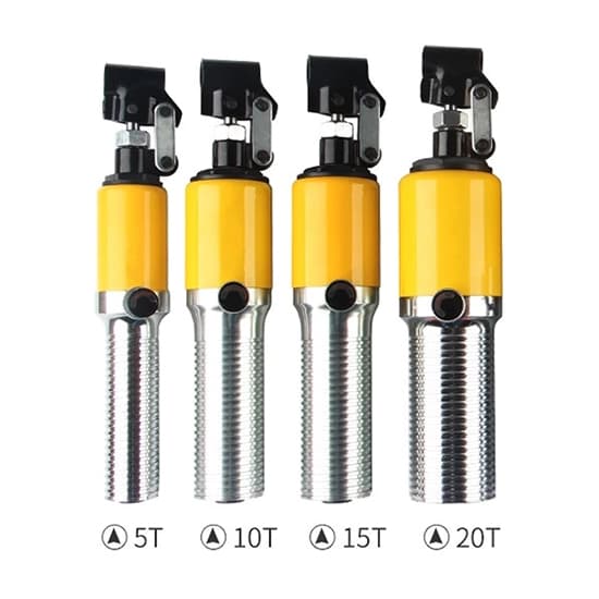
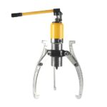
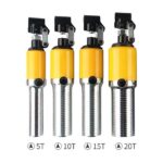
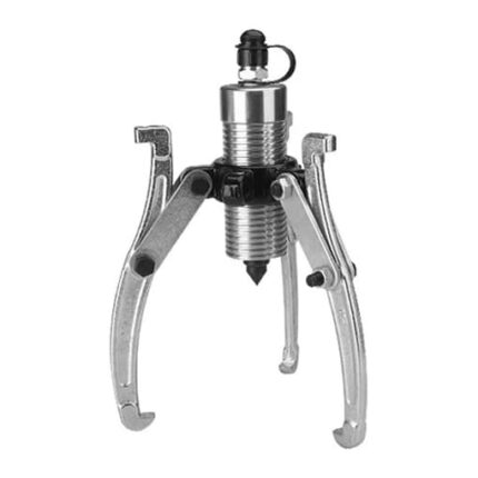
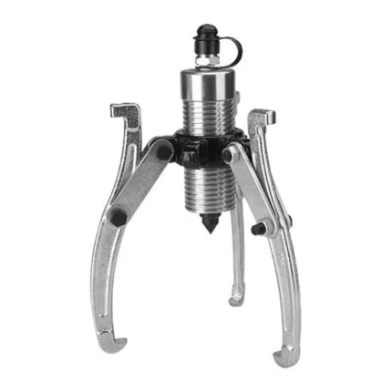
Hydraulic Bearing Puller, 5/10/15/20 Ton
Price range: $40.99 through $218.37
56
People watching this product now!
Description
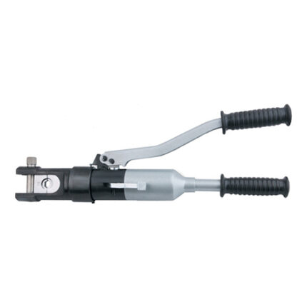
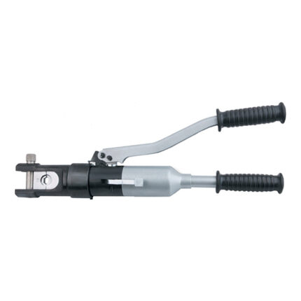
The hydraulic puller is a tool used to pull and removal bearing and gear, output force is 5/10/15/20 ton for selection. It can use 3-jaw or 2-jaw, horizontal or vertical pulling.
Specification
| Model | T-DYF-5 | T-DYF-10 | T-DYF-15 | T-DYF-20 |
| Output Force | 5 Ton | 10 Ton | 15 Ton | 20 Ton |
| Max. Lateral Pull Distance | 200mm | 250mm | 300mm | 350mm |
| Max. Longitudinal Pull Distance | 140mm | 160mm | 180mm | 200mm |
| Stroke | 50mm | 50mm | 50mm | 50mm |
| Thread Diameter | 45.6mm | 60mm | 60mm | 73mm |
| Weight | 6.5 kg | 10.5 kg | 12 kg | 16 kg |
Hydraulic Bearing Puller Structure Diagram
Hydraulic Bearing Puller Dimensions (Unit: mm)
| Model | Total Length | Handle Length | Length of Jaws and Feet |
| T-DYF-5 | 360 | 390 | 240 |
| T-DYF-10 | 375 | 390 | 300 |
| T-DYF-15 | 375 | 390 | 300 |
| T-DYF-20 | 400 | 390 | 300 |
Hydraulic Bearing Puller Use
| Longitudinal Use | Lateral Use |
Hydraulic Bearing Puller Jaws Installation Diagram
| 3-Jaw Installation | 2-Jaw Installation |
Hydraulic Bearing Puller Configurations
| ① pump body*1 | ② handle*1 | ③ Rama circle*1 | ④ thimble*1 | ⑤ screw*6 | ⑥ jaw*3 | ⑦ pull sheet*6 |
Tips: Daily inspection and maintenance for hydraulic bearing puller.
- Check the meshing and wear of all gears. The pitting damage of the tooth surface should not exceed 30% of the meshing surface, and the depth should not exceed 10% of the original tooth thickness. The wear of gear tooth thickness shall not exceed 15%~25% of the original tooth thickness. Check the condition of the bearing. Change the lubricant.
- Check the large and small wheels, lubricate wheel bearings, and eliminate the phenomenon of rail gnawing.
- Check whether the welds in the main beams and end beams are cracked or corroded. The corrosion should not exceed 10% of the original plate thickness. Check whether there are fatigue cracks in all main stressed components and whether various guardrail supports are intact. Tighten the main beam and end beam bolts again.
- Check the reel. The wall wear of the drum shall not exceed 20% of the original wall thickness, and the peak of the rope groove shall not become sharp.
- Tighten all connecting bolts and fastening bolts of the hydraulic bearing puller.